
🔌 NodeMCU ESP8266 WiFi Development Board — Tasmota / ESPHome / WLED / Arduino Ready
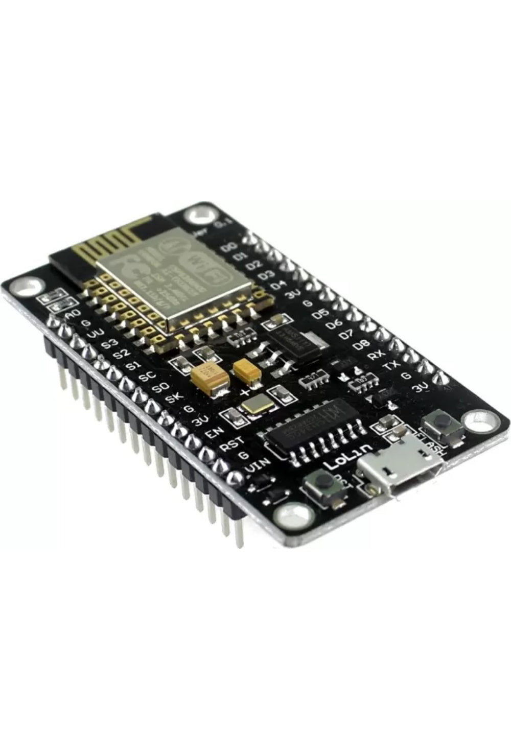
The NodeMCU is a popular ESP8266-based WiFi development board with a built-in USB-to-serial adapter (CP2102/CH340), voltage regulator, and breadboard-friendly pin layout. Flash Tasmota, ESPHome, WLED, or custom Arduino/Lua firmware over USB — no external programmer needed. The go-to board for Home Assistant DIY projects, IoT sensors, LED controllers, and smart home automation. 4MB flash, 11 GPIO pins, 1× ADC.
ESP8266 development boards:
⚡ Key Features
- ESP8266 WiFi SoC — 80/160 MHz Tensilica L106, 2.4 GHz WiFi, 4MB flash memory
- Built-In USB Programmer — CP2102 or CH340 USB-to-serial chip; flash firmware directly via Micro USB cable — no FTDI adapter or soldering needed
- Breadboard Friendly — 30-pin DIP layout fits standard breadboards; wider than the D1 Mini, providing more room for jumper wires
- 11 GPIO Pins — digital I/O, PWM, I²C, SPI, 1-Wire; plus 1× 10-bit ADC (A0, 0–3.3V)
- 3.3V Logic — on-board voltage regulator powers the ESP8266 from 5V USB; GPIO pins are 3.3V (not 5V tolerant)
- Tasmota Ready — flash Tasmota via USB for instant smart switch/sensor functionality with MQTT and Home Assistant auto-discovery
- ESPHome Ready — define your device in YAML, compile, and flash OTA from Home Assistant; supports sensors, relays, LEDs, displays, and more
- WLED Ready — flash WLED for instant control of WS2812B/SK6812 addressable LED strips with 200+ effects and a built-in web UI
- Arduino IDE Compatible — program in C++ using the Arduino framework with thousands of available libraries
- OTA Updates — once initially flashed via USB, all subsequent firmware updates can be pushed wirelessly over WiFi
🏠 Perfect For
LED Strip Controller (WLED)
Flash WLED onto the NodeMCU. Connect a WS2812B LED strip to GPIO2 via a 330Ω resistor. Instant smartphone control with 200+ effects, music sync, and Home Assistant integration.
DIY Sensor Node
Connect a DHT22, BME280, DS18B20, or any I²C/SPI sensor. Flash ESPHome with a simple YAML config. The sensor appears in Home Assistant automatically — temperature, humidity, pressure, soil moisture, anything.
Smart Relay Controller
Wire a relay module (like the 8-channel relay) to the GPIOs. Flash Tasmota for a custom multi-channel smart switch with web UI, MQTT, and Alexa/Google voice control.
Home Assistant Projects
The NodeMCU is the backbone of countless Home Assistant DIY builds — garage door openers, irrigation controllers, mailbox sensors, water tank monitors, energy meters, and more. Pair with a Homekit Box for Apple Home integration.
🔀 NodeMCU vs D1 Mini — Which to Choose?
Both use the same ESP8266 chip and run the same firmware (Tasmota, ESPHome, WLED, Arduino). The main differences are physical:
NodeMCU — larger (48×25mm), 30 pins, more GPIOs broken out, fits breadboards with space on the sides, on-board RST and FLASH buttons. Better for prototyping and projects with multiple sensors/peripherals.
D1 Mini — compact (34×25mm), 16 pins, fewer GPIOs but enough for most single-purpose projects (LED strip, relay, sensor). Better for permanent installations where space is limited (fits inside project boxes and switch enclosures).
🔗 Pair With
D1 Mini ESP8266
Same ESP8266 chip in a smaller form factor. Ideal for permanent installations where space is limited. Same firmware compatibility.
View Product →Homekit Box (HomeBridge Server)
Pre-built Home Assistant / HomeBridge server. Discover and manage your ESPHome devices instantly. Apple Siri + HomeKit integration.
View Product →WS2812B LED Strip (IP20)
5m addressable RGB LED strip. Flash WLED onto the NodeMCU for instant smart lighting with 200+ effects.
View Product →8-Channel Relay Module
Control up to 8 mains circuits from the NodeMCU. Flash Tasmota for MQTT and eWeLink-compatible multi-switch control.
View Product →📋 Technical Specifications
| Product | NodeMCU ESP8266 WiFi Development Board |
| SoC | ESP8266 (Tensilica L106, 80/160 MHz) |
| Flash Memory | 4MB |
| WiFi | 2.4 GHz 802.11 b/g/n |
| GPIO Pins | 11 usable (D0–D8, RX, TX) |
| ADC | 1 × 10-bit (A0, 0–3.3V input range) |
| Interfaces | I²C, SPI, UART, PWM, 1-Wire |
| Operating Voltage | 3.3V (on-board regulator from 5V USB) |
| USB Connector | Micro USB |
| USB-to-Serial Chip | CP2102 or CH340 (varies by batch) |
| Logic Level | 3.3V (NOT 5V tolerant) |
| Board Size | ~48 × 25 mm |
| Pin Count | 30 (15 per side) |
| Compatible Firmware | Tasmota · ESPHome · WLED · Arduino · NodeMCU Lua |
| Home Assistant | ESPHome (native) · Tasmota (MQTT) · WLED integration |
📌 GPIO Pin Reference
| Pin | GPIO | Notes |
|---|---|---|
| D0 | GPIO16 | Wake from deep sleep; no PWM/I²C |
| D1 | GPIO5 | I²C SCL (default) |
| D2 | GPIO4 | I²C SDA (default) |
| D3 | GPIO0 | FLASH button; pulled HIGH at boot |
| D4 | GPIO2 | Built-in LED; WLED data pin; pulled HIGH at boot |
| D5 | GPIO14 | SPI CLK |
| D6 | GPIO12 | SPI MISO |
| D7 | GPIO13 | SPI MOSI |
| D8 | GPIO15 | SPI CS; pulled LOW at boot |
| A0 | ADC0 | Analog input (0–3.3V, 10-bit) |
❓ Frequently Asked Questions
What's the difference between NodeMCU and D1 Mini?
Which USB driver do I need?
Can I flash Tasmota over USB?
Is it compatible with Home Assistant?
Can I power it from a battery?
🤝 Need Help? We're Here for You!
Visit Us
8 Wildebraam Street
Weltevreden Park, Roodepoort
Gauteng, 1709
Build Something Smart 🔌
The ESP8266 board that powers thousands of Home Assistant projects worldwide.